info@dpmachinery.com
0086 15366795302
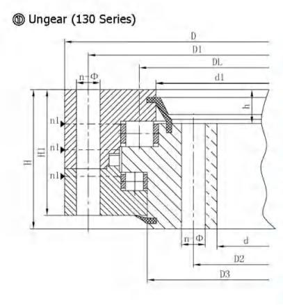
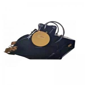
Specific parameters of130 Series Non-Gear Three-Row Roller Slewing Bearing are as follows:
| NO. |
Non gear
DL
mm
|
Dimensions | Mounting Dimensions | Structural Dimension | Gear data | Tooth force |
Weight
kg
|
||||||||||||||||
|
D
mm
|
d
mm
|
H
mm
|
D1
mm
|
D2
mm
|
n |
Ø
mm
|
dm
mm
|
L
mm
|
D3
mm
|
d1
mm
|
n1 |
H1
mm
|
h
mm
|
b
mm
|
x |
M
mm
|
De
mm
|
z | Norm alizing Z10 4N |
Quenching
T10 4N
|
|||
| 1 | 130.25.500 | 634 | 366 | 148 | 598 | 402 | 24 | 18 | M16 | 32 | 474 | 463 | 4 | 10 | 32 | 224 | |||||||
| 2 | 130.25.560 | 694 | 426 | 148 | 658 | 462 | 24 | 18 | M16 | 32 | 534 | 523 | 4 | 10 | 32 | 240 | |||||||
| 3 | 130.25.630 | 764 | 496 | 148 | 728 | 532 | 28 | 18 | M16 | 32 | 604 | 593 | 4 | 10 | 32 | 270 | |||||||
| 4 | 130.25.710 | 844 | 576 | 148 | 808 | 612 | 28 | 18 | M16 | 32 | 684 | 673 | 4 | 10 | 32 | 300 | |||||||
| 5 | 130.32.800 | 964 | 636 | 182 | 920 | 680 | 36 | 22 | M20 | 40 | 770 | 759 | 4 | 10 | 40 | 500 | |||||||
| 6 | 130.32.900 | 1064 | 736 | 182 | 1020 | 780 | 36 | 22 | M20 | 40 | 870 | 859 | 4 | 10 | 40 | 600 | |||||||
| 7 | 130.32.1000 | 1164 | 836 | 182 | 1120 | 880 | 40 | 22 | M20 | 40 | 970 | 959 | 5 | 10 | 40 | 680 | |||||||
| 8 | 130.32.1120 | 1284 | 956 | 182 | 1240 | 1000 | 40 | 22 | M20 | 40 | 1090 | 1079 | 5 | 10 | 40 | 820 | |||||||
| 9 | 130.40.1250 | 1445 | 1055 | 220 | 1393 | 1107 | 45 | 26 | M24 | 48 | 1213 | 1200 | 5 | 10 | 50 | 1200 | |||||||
| 10 | 130.40.1400 | 1595 | 1205 | 220 | 1543 | 1257 | 45 | 26 | M24 | 48 | 1363 | 1350 | 5 | 10 | 50 | 1300 | |||||||
| 11 | 130.40.1600 | 1795 | 1405 | 220 | 1743 | 1457 | 48 | 26 | M24 | 48 | 1563 | 1550 | 6 | 10 | 50 | 1520 | |||||||
| 12 | 130.40.1800 | 1995 | 1605 | 220 | 1943 | 1657 | 48 | 26 | M24 | 48 | 1763 | 1750 | 6 | 10 | 50 | 1750 | |||||||
| 13 | 130.45.2000 | 2221 | 1779 | 231 | 2155 | 1845 | 60 | 33 | M30 | 60 | 1967 | 1945 | 6 | 12 | 54 | 2400 | |||||||
| 14 | 130.45.2240 | 2461 | 2019 | 231 | 2395 | 2085 | 60 | 33 | M30 | 60 | 2207 | 2185 | 6 | 12 | 54 | 2700 | |||||||
| 15 | 130.45.2500 | 2721 | 2279 | 231 | 2655 | 2345 | 72 | 33 | M30 | 60 | 2467 | 2445 | 8 | 12 | 54 | 3000 | |||||||
| 16 | 130.45.2800 | 3021 | 2579 | 231 | 2955 | 2645 | 72 | 33 | M30 | 60 | 2767 | 2745 | 8 | 12 | 54 | 3400 | |||||||
| 17 | 130.50.3150 | 3432 | 2868 | 270 | 3342 | 2958 | 72 | 45 | M42 | 84 | 3104 | 3090 | 8 | 12 | 65 | 5000 | |||||||
| 18 | 130.50.3550 | 3832 | 3268 | 270 | 3742 | 3358 | 72 | 45 | M42 | 84 | 3504 | 3490 | 8 | 258 | 65 | 5680 | |||||||
| 19 | 130.50.4000 | 4282 | 3718 | 270 | 4192 | 3808 | 80 | 45 | M42 | 84 | 3954 | 3940 | 8 | 258 | 65 | 6470 | |||||||
| 20 | 130.50.4500 | 4782 | 4218 | 270 | 4692 | 4308 | 80 | 45 | M42 | 84 | 4454 | 4440 | 8 | 258 | 65 | 7320 | |||||||
4. “K" is addendum reduction coefficient.
Name: Ms Linda Ren
Tel:0086 15366795302
Whatsapp:008615366795302
Email:info@dpmachinery.com
Add:A11-423, China Safety Valley, Lijiang Road South, Xuzhou High-Tech Industrial Development Zone, Jiangsu, China--221000