info@dpmachinery.com
0086 15366795302
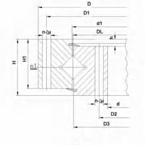
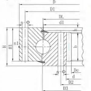
The single row four point contact ball slewing bearing iscomposed of two seat ringS, which design in compactstructure and light weight, steel ball contact with the circularraceway at four point, it can bear the axial force, radial forceand the tilting moment at the same time.It can be used for slewing conveyer, welding manipulator,light & medium duty crane,excavator, and other constructionmachinery.
Note:
NO.
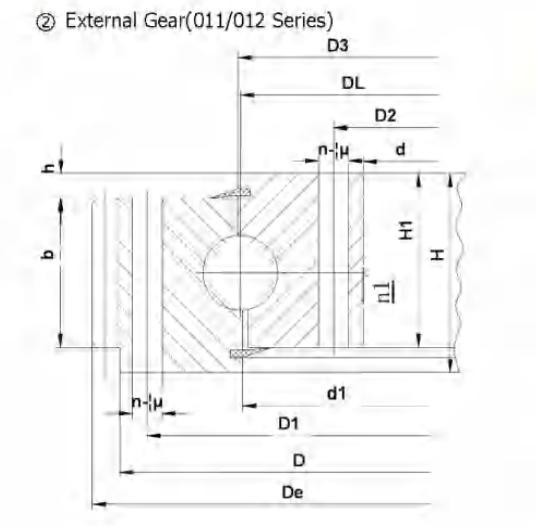
External gear
DL
mm
Dimensions
Mounting Dimensions
Structural Dimension
Gear data
Tooth force
Weight
kg
D
mm
d
mm
H
mm
D1
mm
D2
mm
n
Ø
mm
dm
mm
L
mm
n1
D3
mm
d1
mm
H1
mm
h
mm
b
mm
x
M
mm
De
mm
z
Norm alizing Z10 4N
Quenching
T10 4N
15
011.40.1000
1122
878
100
1078
922
36
22
M20
40
6
1001
998
90
10
80
0.5
10
1188
116
10
14
270
012.40.1000
12
1185.6
96
12
16.7
15'
011.30.1000
1122
878
100
1078
922
36
22
M20
40
6
1001
998
90
10
80
0.5
10
1188
116
10
14
270
012.30.1000
12
1185.6
96
12
16.7
16
011.40.1120
1242
998
100
1198
1042
36
22
M20
40
6
1121
1118
90
10
80
0.5
10
1298
127
10
14
300
012.40.1120
12
1305.6
106
12
16.7
16'
011.30.1120
1242
998
100
1198
1042
36
22
M20
40
6
1121
1118
90
10
80
0.5
10
1298
127
10
14
300
012.30.1120
12
1305.6
106
12
16.7
17
011.45.1250
1390
1110
110
1337
1163
40
26
M24
48
5
1252
1248
100
10
90
0.5
12
1449.6
118
13.5
18.8
420
012.45.1250
14
1453.2
101
15.8
21.9
17"
011.35.1250
1390
1110
110
1337
1163
40
26
M24
48
5
1251
1248
100
10
90
0.5
12
1449.6
118
13.5
18.8
420
012.35.1250
14
1453.2
101
15.8
21.9
18
011.45.1400
1540
1260
110
1487
1313
40
26
M24
48
5
1402
1398
100
10
90
0.5
12
1605.6
131
13.5
18.8
480
012.45.1400
14
1607.2
112
15.5
21.9
18
011.35,1400
1540
1260
110
1487
1313
40
26
M24
48
5
1401
1398
100
10
90
0.5
12
1605.6
131
13.5
18.8
480
012.35.1400
14
1607.2
112
15.8
21.9
19
011.45.1600
1740
1460
110
1687
1513
45
26
M24
48
5
1602
1598
100
10
90
0.5
14
1817.2
127
15.8
21.9
550
012.45.1600
16
1820.8
111
18.1
25
19'
011.35.1600
1740
1460
110
1687
1513
45
26
M24
48
5
1601
1598
100
10
90
0.5
14
1817.2
127
15.8
21.9
550
012.35.1600
16
1820.8
111
18.1
25
20
011.45.1800
1940
1660
110
1887
1713
45
26
M24
48
5
1802
1798
100
10
90
0.5
14
2013.2
141
15.8
21.9
610
012.45.1800
16
2012.8
123
18.1
25
20′
011.35.1800
1940
1660
110
1887
1713
45
26
M24
48
5
1801
1798
100
10
90
0.5
14
2013.2
141
15.8
21.9
610
012.35.1800
16
2012.8
123
18.1
25
21
011.60.2000
2178
1825
144
2110
1891
48
33
M30
60
8
2002
1998
132
12
120
0.5
16
2268.8
139
24.1
33.3
1100
012.60.2000
18
2264.4
123
27.1
37.5
21'
011.40.2000
2178
1825
144
2110
1891
48
33
M30
60
8
2001
1998
132
12
120
0.5
16
2268.8
139
24.1
33.3
1100
012.40.2000
18
2264.4
123
27.1
37.5
22
011.60.2240
2418
2065
144
2350
2131
48
33
M30
60
8
2242
2238
132
12
120
0.5
16
2492.8
153
24.1
33.3
1250
012.60.2240
18
2498.4
136
27.1
37.5
22'
011.40.2240
2418
2065
144
2350
2131
48
33
M30
60
8
2241
2238
132
12
120
0.5
16
2492.8
153
24.1
33.3
1250
012.40.2240
18
2498.4
136
27.1
37.5
1. n1 is the nos of lubricating holes.Oil cupM10x1JB/T7940.1~JB/7940.2.The Oil nipple's location can be change according to the user's application.
2.n- φcan change to tapped hole,the diameter of tapped hole is M,depth is 2M.
3, The tangential tooth force in the form is the max tooth force,the nominal tangential tooth force is 1/2 of the max one.
4. "k" is addendum reduction coefficient.
External Gear 011.012 Series Single-Row Four-Point Contact Ball Slewing Bearing-Part 1
External Gear 011.012 Series Single-Row Four-Point Contact Ball Slewing Bearing-Part 3
Name: Ms Linda Ren
Tel:0086 15366795302
Whatsapp:008615366795302
Email:info@dpmachinery.com
Add:A11-423, China Safety Valley, Lijiang Road South, Xuzhou High-Tech Industrial Development Zone, Jiangsu, China--221000